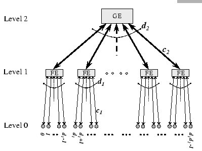
Ethernet-based network is the most widely used local area networking technology. Although standard Ethernet has limited bandwidth in supporting cluster computing, its enhanced versions, such as Fast Ethernet (FE), Gigabit Ethernet (GE) and 10 Gigabit Ethernet provide sufficient bandwidth with a steady upgrade path in building large-scale commodity clusters. Therefore, many self-made large-scale clusters [25,27,26] are using Fast Ethernet and/or its successor as the base of their interconnections. For example, Cluster@TOP500 [28] has conducted an informal survey on choice of cluster interconnects. There are total 380 votes as of July 2001 on this poll, and the result is shown in Figure 6.1. Roughly speaking, 60% of the system designers have voted for Ethernet-based interconnect.
|
Currently, there are two approaches in building a large-scale cluster using the Ethernet-based interconnections. First, using a single high-performance, high port density chassis switch to connect all machines [71]. Second, using a hierarchical network, in which cluster nodes are connected to Fast Ethernet switches and using the Gigabit Ethernet as a backbone network to interconnect all Fast Ethernet switches. Given that the backbone capacity of the interconnection network is greater than the bandwidth demands of the whole cluster, both approaches support a fully connected network with similar performance. In reality, both approaches are suffered from similar architectural constraints that limit their actual performance. In previous chapter, our study of complete exchange on a single router switch has revealed that the buffering mechanism used within the switch could hinder its actual performance, and we have proposed a sub-optimal algorithm (group shuffle exchange) in dealing with the situation.
The hierarchical approach makes use of compatible network technologies, which is a more cost-effective method in incremental scaling of the cluster. With current Ethernet installations, connections between different technologies are commonly bridged by one or more uplink ports, which are add-ons to those ``lower'' end devices. Since faster Ethernet technologies are mutated from the standard Ethernet, so they are using the same mechanism in switching packets. Packet received on an ingress port is switched to the corresponding egress port according to the destination MAC address found at the head of each packet. The switch uses its address lookup table to make this forwarding decision.
Within the Fast Ethernet switch, there are two types of network traffics, either internal traffics or cross-switch traffics. For internal flows, packets are destined to cluster nodes that connect to the same FE switch directly; while for the cross-switch flows, packets are destined to remote cluster nodes that are resided across the network hierarchy. The requirement of having higher channel bandwidth for the uplink limits the switching mechanism adopted on this type of interconnection. As cut-through switching is only possible for ports operate at the same data rate or slower, this is not suitable for the uplink connections and makes the store-and-forward switching be the only feasible solution. However, the change of channel bandwidth between two technologies may induce hot spot since store-and-forward switching causes cumulating of upstream and downstream packets over those uplink ports.
Apparently, even under a node contention-free schedule, sharing of uplinks is needed on a hierarchical network. For instance, all cross-switch traffics are going via the uplinks to the GE switch, packets have to contend for the shared links although they are from distinct sources and to distinct destinations. In theory, under a node contention-free schedule, the distribution of data packets should be well balanced. Thus, any transient congestion over the uplinks could be handled by the buffers in the switches as well as the higher throughput of the uplink connections. However, the distributed nature of the clusters does not guarantee to adhere to a tightly synchronized schedule. Any random delay on scheduling communication events of the complete exchange operation may result in considerably contention. As congestion is handled by the buffers in the switches, therefore, we see that the buffering mechanism plays a critical role in the overall performance of the hierarchical network.
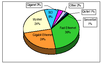
To simplify the discussion, a two-level switch hierarchy as depicted in Figure 6.2 is discussed. For this tree topology, all cluster nodes are the leaf nodes, and are grouped into disjoint sets with